Supplies:
• 216 lights
• 3/4" MDF Board ~ $32 plus cutting fee
• Bolt Cutter
• JB Weld epoxy ~ $12 (I don't own a welder)
• Clamps made from screws and spare wood
• Flat Black Rust-Oleum Spray Paint ~ $5
• Zip Ties (UV Resistant) ~$10
• 30 hours to complete
My Design is based on Matt Johnson's How To Build A Pixel Snowflake Video.

Sketched Snowflake design on 3/4" MDF board. Snowflake end to end is 32" with 1/2" space between lines. (*End product uses straight lines, instead of curved pictured here, for ease in later gluing.) The purpose of the MDF board is to create a JIG that can be used to make several identical snowflakes. One board is enough for several designs. (wreaths, snowflakes, candy canes, etc.)

Drilled out door knob sized holes for the major joints.

Borrowed a friend's router to grind out the lines for the 12 gauge hanger wire.

Used a bolt cutter for the wires ...and since I don't own a welder, I went with JB Weld epoxy. It is super strong and works like a charm. Make sure to completely surround the wire connections (forming a sort of X-shaped epoxy "tube" around them).

I pinched the main joints with some scrap wood and screws to glue them together with pressure. It took 2 separate nights.
In my design, I'm keeping the middle wires for support (Matt cut them out in his design). Here you can also see where I changed from a circular outer ring to a hexagonal shape. (Makes gluing easier)

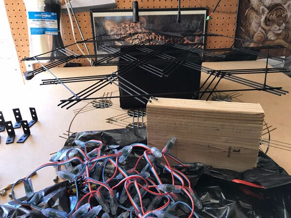
I popped the wooden clamps off and sanded away the splinters. Then sprayed flat black Rust-Oleum spray paint over it to protect from rust and hide the snowflake support frame when the lights are on. (You can see the smaller snowflake under this one ready to be glued.)

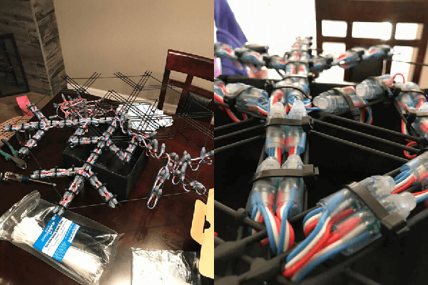
Working on zip-tying the lights: It takes quite some time and took several nights of work.

Here is the finished 32" snowflake with 216 lights attached.

Plugged it in and tested it out. The final 24 lights didn't light up...
It turns out I had the incorrect number on the e682 webpage. Once I updated the number to 216 they all light up.
ALSO, I had to POWER INJECT from the end of the light strand. More on Power Injection can be found here.
Click to see Snowflake Video Test


Back with the better photos!
Here is my LARGE Snowflake Jig. (I did not use the outer circle. I used straight wire to form a hexagon)
From the middle of the snowflake to the end, it's 16 inches. 32" diameter snowflake total.
Here is my SMALL Snowflake Jig.
Small snowflake middle to end is 12 inches. 24" total diameter snowflake.
This is how I cut and arranged the branch wires for more JB weld contact points and overall sturdier design.
Here is how I arranged the lights on my large snowflake: Since the middle of the snowflake fit 4 pixels, it ended up being too far of a stretch from pixel 26 shown to pixel 29. I then would have to extend the wires and solder on each snowflake arm... INSTEAD, I looped the design around so now pixel 28 was close enough to pixel 29 that I didn't need to do anything but continuously zip tie them on.
I continued this pixel pattern all the way around. Each time I came to the end of a strand of 50 pixels, I cut and soldered on the start of the next 50 for better waterproofing.
Here it is flipped over to the back side.
I extended the start pixel upward and added a waterproof connector. The last pixel in the large snowflake is pixel 216. Here, I extended it up and out about 6 feet. (which goes over and plugs into the next small snowflake.) You can also see I added to the end extension the power injection wires and its own waterproof connector. That way power comes from both the first pixel and the last pixel in the snowflake. Since I use 12 volt lights, I haven't had any voltage drop issues.
There really is no wrong way of wiring the lights... It all comes down to your sequencing software. This is how I set up the pixel order in excel for later copying into xLights. I color coordinated the numbers to help me remember which lights go inside certain submodels. Hope this helps!
Great question by the way! I'll get some good photos and a better explaination of how I wired it together in the coming days. Since I chose to keep the middle wires for support, I used them to continue Matt's design into the center of the snowflake (Rather than cut it out). Also, I'll post more on the outer joints... Matt appeared to stop his right when they touch the main part... I continued through for more epoxy support. -pics to come!!!
This is awesome. Thank you! Just need to find the time and money now.
Hi there! It took me 3 days of JB weld epoxy. I did the inner ring first. You completely cover the joints (all around... surround the touching wires to form a “tube of epoxy”) Then, while still wet, I clamped the group with 2 pieces of spare wood (shims work too) one on top and one on the bottom of the frame. Using a screw and a wire nut from below, I tightened it to pinch the wires together. PRO TIP.. these wood pieces snap off and sometimes completely break off when trying to remove them. I found it easier to cut pieces of paper or paper plate so the wood doesn’t stick to the JB weld glue. It’s still a pain to sand the stuck on paper later, but then you can reuse the wood clamps.
day 2, I removed the wood clamps, and JB weld epoxy'd the next outer rings... day three I found it better to just use straight wire instead of Matt's original ring. I removed the snowflake from the MDF board and balanced it on a roll of duct tape and clamped the outer "hexagonal" shape after glueing those in place.
THE SECRET to matching Matt's drawing... lol I slowed down his video during the timelapse part... and found the ruler he used in a perfect position to see it was exactly 32 inches from end to end. Then it was just a matter of measuring how far the "branches" of the snowflakes were. There was some guessing, but for the most part, it came out pretty close. :) Here is the screen shot I used from Matt's video to help me figure out how long each part was. If you'd like, I can get a better photo of mine with a ruler up against it. :) I have a large 32" like Matt's, and a smaller 24" version. He's got the center line plus a line on either side of it spaced exactly .5 inches apart.
Can you better explain the JB Weld and clamping process? I put this off because of the welding aspect and you have me thinking of doing it now.
In fact -- how did you draw it so identical to Matt's? I am really psyched to try this now. Also how did you attach these once completed?